What is Substation Automation?
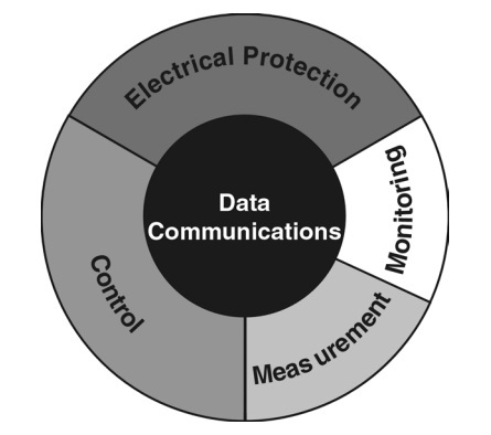
Substation Automation may be best described by referring to Figure 3.1.
Substation Automation, by definition, consists of the following main components:
- Electrical Protection
- Control
- Measurement
- Monitoring
- Data Communications
Substation Automation can be defined as a system for managing, controlling and protecting a power system. This is accomplished by obtaining real-time information from the system, having powerful local and remote control applications and advanced electrical protection. The core ingredients of a Substation Automation system are local intelligence, data communications and supervisory control and monitoring.
The term Substation Automation is actually too restrictive and may be misleading. It is too restrictive in the sense that it refers specifically to a substation only. However, the concepts encompassed in the definition have a much wider application than being limited only to substations. It is applicable to electrical power networks at large, from High Voltage transmission networks, to Medium Voltage distribution networks, to Low Voltage reticulation networks. The term may be misleading in that automation usually refers to some type of process automation, whereas the concepts involved in Substation Automation are quite unique and far removed from process automation, although there is some common ground in the underlying principles.
The term Substation Automation evolved due to the fact that most of the equipment that forms the core of such a system, is located in an electrical substation or switch-room, and these modern, intelligent devices ensure that the need for human presence or intervention in a substation is limited. The components of a Substation Automation system aim to protect monitor and control a typical electrical substation.
(Note: The term “substation” will be used throughout the text to describe mainly a building housing electrical switchgear, but it may also include switchgear housed in some sort of enclosure, for example a stand-alone Ring Main Unit, etc.)
Electrical Protection
Electrical Protection is still one of the most important components of any electrical switchgear panel, in order to protect the equipment and personnel, and to limit damage in case of an electrical fault.
Electrical protection is a local function, and should be able to function independently of the Substation Automation system if necessary, although it is an integral part of Substation Automation under normal conditions. The functions of electrical protection should never be compromised or restricted in any Substation Automation system.
Control
Control includes local and remote control. Local control consists of actions the control device can logically take by itself, for example bay interlocking, switching sequences and synchronizing check. Human intervention is limited and the risk of human error is greatly reduced.
Local control should also continue to function even without the support of the rest of the Substation Automation system. Commands can be given directly to the remote controlled devices, for example open or close a circuit breaker. Relay settings can be changed via the system, and requests for certain information can be initiated form the SCADA station(s). This eliminates the need for personnel to go to the substation to perform switching operations, and switching actions can be performed much faster, which is a tremendous advantage in emergency situations.
A safer working environment is created for personnel, and huge production losses may be prevented. In addition, the operator or engineer at the SCADA terminal has a holistic overview of what is happening in the power network throughout the plant or factory, improving the quality of decision-making.
[For further description, please see the next parts of this series (Substation Automation)]


